Survival Table | Windloading
Gabriel antenna windloading and environmental ratings are listed below. The windload tables address all the windload criteria associated to the Standard and High Performance QuickFire models. In addition, you will find larger antenna diameter information for existing legacy products currently in operation worldwide.
Operational Temperature
Gabriel antennas are designed to operate at a minimum -40° F to +122° F (-40° C to + 50° C) per ANSI/TIA-222.
Vertical Tower Mount Antennas Survival Ratings (1.) Wind Deflection (2.)
| Antenna Type | Wind | Ice | Wind | Max. Deflection deg. | |||
| mph | (km/hr) | in. | (mm) | mph | (km/hr) | ||
| Directional Flat Panel Antennas | 125 | (201) | 1 | (25) | 70 | -112 | Note 1 |
| Solid Parabolic Antennas | 125 | (201) | 1 | (25) | 70 | -112 | Note 1 |
| “SE” Series Parabolic Antennas | |||||||
| Standard & High Performance 2 – 4 ft | 125 | (201) | 1 | (25) | 100 | 161 | 0.1° |
| Standard & High Performance 6 – 12 ft | 125 | (201) | 1 | (25) | 70 | 112 | 0.1° |
| Standard with H.D. Radome | 125 | (201) | 1 | (25) | 70 | 112 | 0.1° |
- Per ANSI/TIA-222.
- The above list of wind deflections applies to all sizes and frequencies. The ANSI/TIA operational wind speeds are never less than those listed in the table, but may be much higher. The allowable operational deflection for dish antennas is based on the antenna movement that would cause the signal to drop 10 dB. As the main beam of the antenna becomes wider, more deflection is allowed before the signal drops 10 dB. Smaller dishes and lower frequencies often have substantially improved operational wind speed. Check with your mWAVE – Gabriel and Mark Sales contact for specific information.
* Trademark of DuPont
NOTE: Mechanical Specifications are subject to change without notification.
“GL”† & “GH” Grid Series Antennas
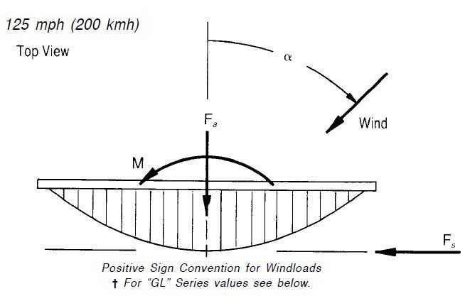
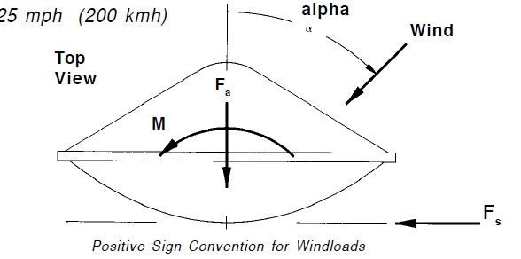
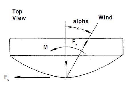
Approximate Wind Forces at 125 mph (200 kmh)
| Grid Antenna without Ice | |||||||||
| Antenna Diameter | Wind Angle | Axial Force | Side Force | Twisting Moment | |||||
| ft | m | Degree | Fa | FS | M | ||||
| lb | N | lb | N | ft-lb | N-m | ||||
| 3 | 0.9 | 0 | 180 | 810 | 0 | 0 | 0 | 0 | |
| 70 | 52 | 230 | 93 | 410 | 59* | 79* | |||
| 115 | -79 | -350 | 95* | 420* | 57 | 78 | |||
| 180 | -200* | 890* | 0 | 0 | 0 | 0 | |||
| 4 | 1.2 | 0 | 310 | 1360 | 0 | 0 | 0 | 0 | |
| 70 | 87 | 390 | 155 | 690 | 127* | 172* | |||
| 115 | -133 | -590 | 160* | 710* | 124 | 169 | |||
| 180 | -330* | -1490* | 0 | 0 | 0 | 0 | |||
| 6 (2) | 1.8 | 0 | 710 | 3100 | 0 | 0 | 0 | 0 | |
| 70 | 200 | 890 | 360 | 1600 | 450* | 610* | |||
| 115 | -310 | -1360 | 370* | 1640* | 440 | 590 | |||
| 180 | -770* | -3400* | 0 | 0 | 0 | 0 | |||
| 8 | 2.4 | 0 | 1200 | 5300 | 0 | 0 | 0 | 0 | |
| 70 | 340 | 1520 | 610 | 2700 | 990* | 1340* | |||
| 115 | -520 | 2300 | 630* | 2800* | 970 | 1310 | |||
| 180 | -1310* | -5800* | 0 | 0 | 0 | 0 | |||
| 10 | 3 | 0 | 1900 | 8500 | 0 | 0 | 0 | 0 | |
| 70 | 540 | 2400 | 990 | 4300 | 1960* | 2700* | |||
| 115 | -820 | -3700 | 990* | 4400* | 1920 | 2600 | |||
| 180 | -2100* | -9200* | 0 | 0 | 0 | 0 | |||
| 12 | 3.7 | 0 | 2700 | 11900 | 0 | 0 | 0 | 0 | |
| 70 | 760 | 3400 | 1350 | 6000 | 3300* | 4400* | |||
| 115 | -1150 | -5100 | 1390* | 6200* | 3200 | 4300 | |||
| 180 | -2900* | -13000* | 0 | 0 | 0 | 0 | |||
Grid Antenna with 1/2 in. (25mm) Radial Ice**
| Antenna Diameter | Wind Angle | Axial Force | Side Force | Twisting Moment | |||||
| ft | m | Degree | Fa | FS | M | ||||
| lb | N | lb | N | ft-lb | N-m | ||||
| 3 | 0.9 | Contact Sales Representative for more information | |||||||
| 4 | 1.2 | 0 | 750 | 3300 | 0 | 0 | 0 | 0 | |
| 60 | 780* | 3500* | 148 | 660 | -137 | -186 | |||
| 125 | -230 | -1020 | 240* | 1060* | 300* | 400* | |||
| 180 | -530 | -2400 | 0 | 0 | 0 | 0 | |||
| 6 (2) | 1.8 | 0 | 1730 | 7700 | 0 | 0 | 0 | 0 | |
| 60 | 1810* | 8100* | 340 | 1520 | -480 | -650 | |||
| 125 | -530 | -2400 | 550* | 2600* | 1050* | 1420* | |||
| 180 | -1230 | -5500 | 0 | 0 | 0 | 0 | |||
| 8 | 2.4 | 0 | 2900 | 13100 | 0 | 0 | 0 | 0 | |
| 60 | 3100* | 13700* | 580 | 2600 | -1070 | -1440 | |||
| 125 | -900 | -4000 | 940* | 4200* | 2300* | 3100* | |||
| 180 | -2100 | -9300 | 0 | 0 | 0 | 0 | |||
| 10 | 3 | 0 | 4600 | 21000 | 0 | 0 | 0 | 0 | |
| 60 | 4900* | 22000* | 920 | 4100 | -2100 | -2900 | |||
| 125 | -1430 | -6400 | 1480* | 6600* | 4600* | 6200* | |||
| 180 | -3300 | 14700 | 0 | 0 | 0 | 0 | |||
| 12 | 3.7 | 0 | 6500 | 29000 | 0 | 0 | 0 | 0 | |
| 60 | 6800* | 30000* | 1290 | 5700 | -3500 | -4800 | |||
| 125 | -2000 | -8900 | 2100* | 9300* | 7700* | 10400* | |||
| 180 | -4600 | -21000 | 0 | 0 | 0 | 0 | |||
Standard Antenna
| Standard Antenna without radome | |||||||||
| Antenna Diameter | Wind Angle | Axial Force | Side Force | Twisting Moment | |||||
| ft | m | Degree | Fa | FS | M | ||||
| lb | N | lb | N | ft-lb | N-m | ||||
| 2 | 0.6 | 0 | 290 | 1280 | 0 | 0 | 0 | 0 | |
| 60 | 310* | 1390* | 49 | 220 | -39 | -53 | |||
| 125 | -82 | -360 | 87* | 390* | 65* | 89* | |||
| 180 | -193 | -860 | 0 | 0 | 0 | 0 | |||
| 2.5 | 0.8 | 0 | 390 | 1750 | 0 | 0 | 0 | 0 | |
| 60 | 430* | 1910* | 67 | 300 | -63 | -86 | |||
| 125 | -112 | -500 | 119* | 530* | 106* | 143* | |||
| 180 | -270 | -1180 | 0 | 0 | 0 | 0 | |||
| 4 | 1.2 | 0 | 960 | 4300 | 0 | 0 | 0 | 0 | |
| 60 | 1050* | 4700* | 163 | 720 | -240 | -320 | |||
| 125 | -270 | -1210 | 209* | 1290* | 400* | 540* | |||
| 180 | -640 | -2900 | 0 | 0 | 0 | 0 | |||
| 6 | 1.8 | 0 | 2000 | 9100 | 0 | 0 | 0 | 0 | |
| 60 | 2200* | 9900* | 350 | 1550 | -750 | -1010 | |||
| 125 | -580 | -2600 | 620* | 2800* | 1250* | 1690* | |||
| 180 | -1380 | -6100 | 0 | 0 | 0 | 0 | |||
| 6 | 1.8 | 0 | 2240 | 9970 | 0 | 0 | 0 | 0 | |
| Deep Dish Cat. “A” | 60 | 2440* | 10860* | 380 | 1690 | -850 | -1150 | ||
| 125 | -630 | -2800 | 680* | 3030* | 1430* | 1940* | |||
| 180 | -1510 | -6720 | 0 | 0 | 0 | 0 | |||
| 8 | 2.4 | 0 | 3400 | 15200 | 0 | 0 | 0 | 0 | |
| 60 | 3700* | 16600* | 580 | 2600 | -1600 | -2200 | |||
| 125 | -970 | -4300 | 1030* | 4600* | 2700* | 3600* | |||
| 180 | -2300 | -10200 | 0 | 0 | 0 | 0 | |||
| 10 | 3 | 0 | 5500 | 24000 | 0 | 0 | 0 | 0 | |
| 60 | 6000* | 27000* | 930 | 4100 | -3200 | -4400 | |||
| 125 | -1550 | -6900 | 1650* | 7300* | 5400* | 7400* | |||
| 180 | -3700 | -16300 | 0 | 0 | 0 | 0 | |||
| 12 | 3.7 | 0 | 7600 | 34000 | 0 | 0 | 0 | 0 | |
| 60 | 8400* | 37000* | 1300 | 5800 | -5400 | -7300 | |||
| 125 | -2200 | -9700 | 2300* | 10300* | 9000* | 12200* | |||
| 180 | -5100 | 23000 | 0 | 0 | 0 | 0 | |||
| 15 | 4.6 | 0 | 12500 | 56000 | 0 | 0 | 0 | 0 | |
| “A” Frame Series Only | 60 | 13700* | 61000* | 2100 | 9500 | -11300 | -15300 | ||
| 125 | -3600 | -15800 | 3800* | 16800* | 18900* | 26000* | |||
| 180 | -8400 | 37000 | 0 | 0 | 0 | 0 | |||
| Standard Antenna with radome | |||||||||
| Antenna Diameter | Wind Angle | Axial Force | Side Force | Twisting Moment | |||||
| ft | m | Degree | Fa | FS | M | ||||
| lb | N | lb | N | ft-lb | N-m | ||||
| 2 | 0.6 | 0 | 163* | 720* | 0 | 0 | 0 | 0 | |
| 50 | 102 | 460 | 100* | 440* | -18 | -25 | |||
| 100 | 9 | 38 | 75 | 330 | 76* | 103* | |||
| 180 | -125 | -550 | 0 | 0 | 0 | 0 | |||
| 2.5 | 0.8 | 0 | 220* | 990* | 0 | 0 | 0 | 0 | |
| 50 | 141 | 630 | 137* | 610* | -30 | -40 | |||
| 100 | 12 | 53 | 102 | 460 | 122* | 166* | |||
| 180 | -171 | -760 | 0 | 0 | 0 | 0 | |||
| 4 | 1.2 | 0 | 540* | 2400* | 0 | 0 | 0 | 0 | |
| 50 | 340 | 1520 | 330* | 1480* | -112 | -152 | |||
| 100 | 29 | 128 | 250 | 1110 | 460* | 630* | |||
| 180 | -420 | -1850 | 0 | 0 | 0 | 0 | |||
| 6 | 1.8 | 0 | 1160* | 5200* | 0 | 0 | 0 | 0 | |
| 50 | 730 | 3300 | 710* | 3200* | -350 | -480 | |||
| 100 | 61 | 270 | 530 | 2400 | 1450* | 1960* | |||
| 180 | -890 | -4000 | 0 | 0 | 0 | 0 | |||
| 6 | 1.8 | 0 | 1270* | 5200* | 0 | 0 | 0 | 0 | |
| Deep Dish Cat. “A” | 50 | 800 | 3300 | 780* | 3470* | -400 | -540 | ||
| 100 | 70 | 270 | 580 | 2580 | 1650* | 2240 | |||
| 180 | -970 | -4000 | 0 | 0 | 0 | 0 | |||
| 8 | 2.4 | 0 | 1930* | 8600* | 0 | 0 | 0 | 0 | |
| 50 | 1220 | 5400 | 1180* | 5300* | -750 | -1020 | |||
| 100 | 102 | 450 | 890 | 3900 | 3100* | 4200* | |||
| 180 | -1480 | -6600 | 0 | 0 | 0 | 0 | |||
| 10 | 3 | 0 | 3100* | 13800* | 0 | 0 | 0 | 0 | |
| 50 | 1950 | 8700 | 1900* | 8400* | -1520 | -2100 | |||
| 100 | 164 | 730 | 1420 | 6300 | 6300* | 8500* | |||
| 180 | -2400 | -10600 | 0 | 0 | 0 | 0 | |||
| 12 | 3.7 | 0 | 4300* | 19300* | 0 | 0 | 0 | 0 | |
| 50 | 2700 | 12200 | 2700* | 11800* | -2500 | -3400 | |||
| 100 | 230 | 1020 | 1990 | 8800 | 10400* | 14200* | |||
| 180 | -3300 | -14800 | 0 | 0 | 0 | 0 | |||
* Indicates maximum value.
Note 1 The above windloads are typical for most applications. For some models, the windloads may vary from this table.
Note 2 Some 6 ft. (1.8m) diameter models meeeting Category “A” criteria, utilize oversized reflectors. Contact your mWAVE Sales person for these values.
“Approximate Wind Forces at 125 mph (200 kmh)
(Forces based on antennas e/w planar radomes)”
High Performance Antenna
| High Performance Antenna Windload | |||||||||
| Antenna Diameter | Wind Angle | Axial Force | Side Force | Twisting Moment | |||||
| ft | m | Degree | Fa | FS | M | ||||
| lb | N | lb | N | ft-lb | N-m | ||||
| 1 | 0.3 | 0 | 76* | 338* | 0 | 0 | 0 | 0 | |
| 90 | -7 | -31 | 43* | 191* | 13 | 18 | |||
| 105 | -30 | -134 | 39 | 174 | 15* | 20* | |||
| 180 | -60 | -267 | 0 | 0 | 0 | 0 | |||
| 1.5 | 0.5 | 0 | 145* | 632* | 0 | 0 | 0 | 0 | |
| 90 | -13 | -58 | 76* | 338* | 28 | 38 | |||
| 105 | -54 | -240 | 70 | 312 | 32* | 46* | |||
| 180 | -112 | -498 | 0 | 0 | 0 | 0 | |||
| 2 | 0.6 | 0 | 240* | 1068* | 0 | 0 | 0 | 0 | |
| 90 | -22 | -98 | 123* | 547* | 55 | 75 | |||
| 105 | -88 | -392 | 111 | 494 | 62* | 84* | |||
| 180 | -186 | -828 | 0 | 0 | 0 | 0 | |||
| 2.5 | 0.8 | 0 | 340* | 1513* | 0 | 0 | 0 | 0 | |
| 90 | -32 | -142 | 176* | 783* | 93 | 126 | |||
| 105 | -128 | -570 | 159 | 708 | 106* | 144* | |||
| 180 | -270 | -1202 | 0 | 0 | 0 | 0 | |||
| 4 | 1.2 | 0 | 790* | 3516* | 0 | 0 | 0 | 0 | |
| 90 | -73 | -325 | 400* | 1780* | 300 | 407 | |||
| 105 | -290 | -1291 | 360 | 1602 | 350* | 475* | |||
| 180 | -620 | -2759 | 0 | 0 | 0 | 0 | |||
| 6 | 1.8 | 0 | 1680* | 7477* | 0 | 0 | 0 | 0 | |
| 90 | -154 | -685 | 820* | 3649* | 850 | 1153 | |||
| 105 | -610 | -2715 | 740 | 3293 | 990* | 1352* | |||
| 180 | -1330 | -5919 | 0 | 0 | 0 | 0 | |||
| 8 | 2.4 | 0 | 2800* | 12500* | 0 | 0 | 0 | 0 | |
| 90 | -260 | -1140 | 1370* | 6100* | 1820 | 2500 | |||
| 105 | -1010 | -4500 | 1230 | 5500 | 2100* | 2900* | |||
| 180 | -2200 | -9800 | 0 | 0 | 0 | 0 | |||
| 10 | 3 | 0 | 4500* | 20000* | 0 | 0 | 0 | 0 | |
| 90 | -410 | -1820 | 2200* | 9800* | 3700 | 5000 | |||
| 105 | -1620 | -7200 | 1960 | 8700 | 4300* | 5800* | |||
| 180 | -3500 | -15700 | 0 | 0 | 0 | 0 | |||
| 12 | 3.7 | 0 | 6300* | 28000* | 0 | 0 | 0 | 0 | |
| 90 | -570 | -2600 | 5000* | 13700* | 6100 | 8300 | |||
| 105 | -2300 | -10100 | 4500 | 12200 | 7200* | 9700* | |||
| 180 | -4900 | -22000 | 0 | 0 | 0 | 0 | |||
Contact your mWAVE Sales Engineer for 15-ft (4.6) Windload Values and Ultra High Performance Antenna model values
NOTE
* Indicates maximum value.
“Note: The above windloads are typical for most applications. For some models, the windloads may vary from this table.”
“Note 1: Some 6 ft. (1.8) diameter “”A”” Frame High Performance and Ultra High Performance antennas, use correction factors of 1.09 for Fa and Fs and 1.14 for M.”
“Note 2: Some 6 ft. (1.8) diameter antenna models meeting Category “”A”” criteria, utilize oversized reflectors.
Contact your Gabriel Sales Engineer for these values.”